

 See My Latest Article on HelloNation
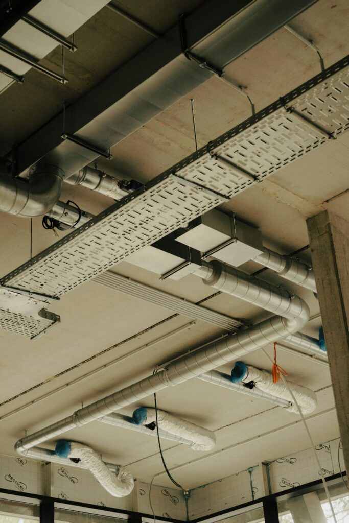
Mechanical construction drawings show how a building’s heating, cooling, ventilation, plumbing, and related systems are arranged, sized, connected, and controlled. They translate design decisions into coordinated instructions that contractors, inspectors, facility staff, and future repair workers can understand.
For residents, property owners, and building users in Rochester, these drawings can help explain why equipment is located in a particular room, how air moves through a building, and what information is available before construction or renovation begins.
What systems appear on mechanical drawings?
Mechanical drawings commonly document building systems that move air, water, heat, fuel, or exhaust. The exact contents depend on the project, but a drawing set may include:
- Heating systems, including boilers, furnaces, heat pumps, radiators, and unit heaters
- Air-conditioning equipment and refrigerant piping
- Ventilation equipment, ductwork, louvers, and exhaust fans
- Plumbing supply, drainage, and vent piping
- Natural gas or other fuel piping
- Fire protection piping where included in the mechanical design
- Temperature controls, sensors, valves, and automatic operating sequences
- Equipment schedules and installation details
- Coordination information showing how mechanical work fits with structural and architectural elements
A small residential renovation may have only a few mechanical sheets. A larger apartment, institutional, or commercial project can include separate plans for heating, ventilation, plumbing, controls, and equipment details.
How are mechanical drawings organized?
The first sheets usually explain how to read the rest of the set. A cover sheet or general notes sheet may identify the project, drawing scale, applicable standards, abbreviations, symbols, and design assumptions.
Mechanical drawings are often identified by letters such as “M” for mechanical, “P” for plumbing, or “FP” for fire protection. The exact naming system varies by designer and project.
A drawing title block typically shows:
- Project name and location
- Sheet title and drawing number
- Drawing scale
- Date of issue
- Revision history
- Designer or engineering firm information
- Approval, review, or permit references when applicable
The revision block matters because construction documents can change after an initial issue. A cloud, triangle, delta symbol, or written note may identify an area that has been revised. Older printed sheets should not automatically be treated as current.
What does a mechanical floor plan show?
A mechanical floor plan places equipment, pipes, ducts, and other components on a floor-by-floor view of the building. It is similar to an architectural floor plan but focuses on building systems rather than room finishes or furniture.
A plan may show the location of:
- Air-handling units and rooftop equipment
- Furnaces, boilers, water heaters, and pumps
- Supply, return, and exhaust ductwork
- Heating and cooling piping
- Plumbing fixtures and branch piping
- Mechanical rooms, shafts, chases, and service clearances
- Thermostats, control panels, dampers, and access panels
Lines are usually labeled with abbreviations, sizes, flow directions, or system names. For example, a duct may be identified as supply air, return air, outside air, or exhaust air. A pipe may be marked by its purpose, such as domestic cold water, hot water, heating water, condensate, or sanitary drainage.
The drawing may not show every physical feature at full size. Some components are represented with symbols or simplified lines so that the overall system can be read clearly.
How do sections and details add information?
Plans show where components are located from above, but sections and details explain how they are installed vertically or assembled.
A section may show:
- Ductwork passing through a ceiling or wall
- Pipe elevations and slope
- Equipment connections
- Roof penetrations
- Floor drains and plumbing stacks
- Clearances around boilers, furnaces, or serviceable equipment
- Insulation thickness and protective coverings
- Firestopping or rated-wall conditions
Details are enlarged drawings of specific installations. A detail might explain how a duct connects to an air grille, how a pipe is supported, or how condensate is routed from cooling equipment.
Section and detail references usually appear as a numbered or lettered symbol on the plan. The matching number or letter directs the reader to another part of the drawing set.
What are equipment schedules?
Equipment schedules summarize important information about mechanical units. They are often presented as tables rather than floor plans.
A schedule may identify:
- Equipment tag or reference number
- Manufacturer or approved equipment basis
- Model information
- Heating or cooling capacity
- Airflow in cubic feet per minute
- Electrical voltage and phase
- Fuel type
- Water flow or pressure requirements
- Weight and approximate dimensions
- Sound or performance requirements
- Required accessories, filters, controls, or insulation
The equipment tag connects the schedule to the plan. For example, a unit labeled “AHU-1” on a drawing should correspond to the row for “AHU-1” in the air-handling-unit schedule.
Schedules are useful because the plan may only show the location and outline of a piece of equipment. The schedule supplies the performance information needed for selection, ordering, installation, and testing.
What do symbols, tags, and abbreviations mean?
Mechanical drawings use a standard-looking visual language, but symbols can vary between designers. A legend or abbreviation list should be consulted before interpreting an unfamiliar mark.
Common information includes:

- Arrows showing air or fluid direction
- Dashed lines indicating concealed or existing work
- Solid lines indicating new visible or primary work
- Circles, squares, or letters representing equipment and devices
- Pipe or duct size labels
- Elevation marks showing height above a reference level
- Valve, damper, cleanout, and access-panel symbols
- Detail bubbles that direct the reader to an enlarged view
- Section markers that connect plans with vertical cuts
A line by itself does not always indicate a specific material or system. Labels, legends, notes, and schedules must be read together.
How do the drawings show heating and ventilation?
Heating and ventilation information is especially relevant in a cold-weather climate. Drawings may show how outdoor air enters a building, how stale air is exhausted, and how heated or conditioned air is distributed.
A ventilation plan can identify:
- Outside-air intakes
- Exhaust outlets
- Supply and return grilles
- Duct routes and dimensions
- Fans and air-handling equipment
- Dampers and balancing devices
- Filters and access doors
- Fire or smoke damper locations
- Airflow quantities for individual rooms or zones
Heating plans may show boilers, furnaces, heat pumps, radiators, baseboard units, radiant tubing, or hydronic piping. They can also show zoning arrangements, which explain how different areas receive separate temperature control.
Mechanical drawings do not always guarantee that every room will feel identical. Actual comfort can also depend on insulation, windows, air sealing, thermostat location, system balancing, and how the building is used.
What plumbing information is included?
Plumbing drawings show how water enters the building, reaches fixtures, and leaves through drainage and vent systems.
Typical information includes:
- Domestic water supply piping
- Hot-water circulation piping
- Sanitary drainage and vent piping
- Stormwater piping where included
- Floor drains and cleanouts
- Sumps, ejectors, and backflow-prevention devices
- Fixture locations and connection sizes
- Pipe slopes and invert elevations
- Water heaters, pumps, and storage tanks
Drainage lines often require slope, while pressurized supply lines may be routed more flexibly. Drawings can also identify shutoff valves and access points that become useful during maintenance or emergencies.
What can drawings reveal about an existing building?
Renovation drawings may distinguish between existing, new, relocated, and demolished work. This distinction is important in older housing and mixed-age neighborhoods, where concealed conditions may differ from original records.
Existing conditions may include undersized ducts, abandoned piping, limited ceiling space, inaccessible valves, or equipment that does not match older documentation. Drawings can identify intended improvements, but field verification is still necessary before walls or ceilings are opened.
For property owners reviewing a project, the most useful questions are often practical: Which systems are new? Which remain? Where are shutoffs and access panels? What equipment requires regular maintenance? Which areas will lose ceiling height or storage space?
Why are coordination and revisions important?
Mechanical systems compete for limited space with beams, wiring, ceilings, lighting, insulation, and architectural finishes. Coordination drawings help reduce conflicts before installation.
A coordinated set may show that a duct must pass below a beam, a pipe must be rerouted around electrical equipment, or an access panel must remain reachable after drywall is installed.
Revisions are equally significant. A changed equipment size can affect structural support, electrical service, duct dimensions, noise, or maintenance clearances. Reading the latest dated drawings and related written specifications is essential for understanding the intended installation.
Mechanical construction drawings are therefore more than maps of pipes and equipment. They are a record of how a building is expected to function: how it is heated, ventilated, supplied with water, drained, controlled, maintained, and adapted to the building’s physical constraints.